If you’ve ever worked with high-voltage (HV) transformers—whether as a maintenance technician, a project engineer, or someone who depends on the reliability of the power grid—you know that insulation is the backbone of these machines. A 230kV transformer in a substation in the Midwest that goes down unexpectedly can cause hours of outages for a small city, cost utility companies thousands of dollars in lost revenue, and even pose safety risks to crews on site. That’s why, as someone who’s been an HV transformer supplier for 12 years, I can’t stress enough how critical regular insulation resistance testing is to keeping these assets running. Over the years, I’ve sat through more than a handful of field calls where a client’s transformer failed prematurely, and when we dug into the root cause, it almost always traced back to missed or incorrect insulation resistance measurements. High-voltage Transformer
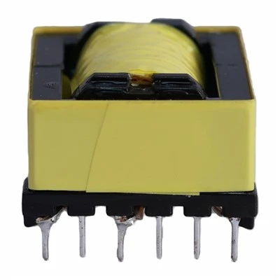
Today, I want to walk you through exactly how to measure the insulation resistance of an HV transformer, not just as a textbook procedure, but as something I’ve seen work (and sometimes fail) in real, messy field conditions. I’ll cover pre-test prep, step-by-step testing, what the numbers actually mean, and common mistakes I still see new technicians make. Most importantly, I’ll tie this all back to why this test isn’t just a box to check for compliance—it’s a way to extend the life of your transformer, avoid costly downtime, and keep your teams safe.
First, let’s start with why insulation resistance testing matters for HV transformers, specifically. Insulation in these units isn’t just a single layer; it’s a complex system of oil-impregnated paper, pressboard, bushings, and the varnish that coats the windings. Over time, this system breaks down from things like moisture ingress, thermal stress from loading, contamination from dirt or sludge in the oil, or even manufacturing defects that only show up years later. The insulation resistance test works by applying a known DC voltage between the energized parts of the transformer (the windings) and the grounded parts (the tank, core, and any grounded shields) and measuring how much current flows through the insulation. The inverse of that current (resistance) tells you how “healthy” the insulation is: higher resistance means less leakage current, which means your insulation is in good shape.
But here’s the thing: this is not a test you can rush. I once worked with a new technician at a client site who tried to test a 115kV transformer right after draining its oil to replace a filter. He didn’t wait for the tank to cool down, he skipped discharging the windings, and he didn’t cover the bushings. We almost had a safety incident when he tried to hook up the megohmmeter and got a nasty jolt from residual charge. That’s why pre-test preparation is non-negotiable.
Let’s break down that pre-test step by step, because skipping any of these is a quick path to bad data or injury. First, safety is number one. HV transformers are built to hold a charge for hours, sometimes even days, after being de-energized. Before you do anything, lock out and tag out (LOTO) the transformer, disconnect it from the grid, and confirm that all high-voltage leads are properly isolated. I always recommend using a voltage detector rated for at least 150% of the transformer’s maximum voltage to double-check that there’s no residual charge. Even if you think you disconnected it, that charge can hide in the windings or capacitors inside the bushings.
Next, prepare the test environment. Insulation resistance readings are highly temperature-dependent—oil and paper insulation’s resistance drops about 50% for every 10°C increase in temperature. So you need to record the ambient temperature, the top-oil temperature, and the winding temperature before testing. I keep a small digital thermometer and a temperature probe in my test bag for this, because guessing the temperature will throw your readings off. Also, you need to make sure the transformer’s bushing surfaces are clean and dry. A layer of dust or oil residue on a bushing can create a parallel leakage path that will make your insulation resistance reading artificially low. I always bring a lint-free cloth and isopropyl alcohol to wipe down the bushings before testing; it takes two minutes and saves you from getting a wrong number that makes you think your transformer is failing when it’s just dirty.
Then, choose the right test equipment. You can’t use a standard multimeter for this—you need a megohmmeter (megger) rated for at least twice the transformer’s maximum operating voltage, and preferably higher. For a 115kV transformer, that means a 2500V or 5000V megger; for a 230kV unit, you’ll want a 10,000V megger. The megger should also have an analog or digital display that can hold a reading for 60 seconds, because the insulation resistance doesn’t stabilize right away.
Now, for the test setup itself. The standard test configuration for most HV transformers is what we call the “winding to tank and core” test, where you connect the megger’s positive lead to all three high-voltage bushing leads (or isolate one winding at a time if it’s a multi-winding unit) and the negative lead to the transformer’s grounded tank and core. If you’re testing a distribution transformer, that’s straightforward, but for large power transformers, you might also test between individual windings (like primary to secondary) to spot faults between windings. One common mistake I see is forgetting to disconnect any auxiliary equipment, like pressure relief valves or temperature sensors, that might have connections to ground. Those can create a parallel path for current and skew your results. I always double-check the schematic of the transformer before hooking up the megger to make sure I’m not connecting to any unintended grounds.
Once everything is set up, you need to discharge any residual charge again—even if you checked earlier, sometimes moving leads can reintroduce a small charge. Hold the discharge wand to the tank, and gently touch the end to each bushing lead for 10 seconds to be sure. Now you’re ready to start the test. Here’s where I emphasize the 60-second reading, and sometimes the 10-minute reading, not just the immediate one. When you apply DC voltage, the insulation goes through three phases: the initial capacitive current (which flows right away and drops off quickly), the absorption current (which flows slower, as the voltage polarizes the insulation molecules), and the leakage current (which is steady, and what you want to use for your final reading). So the 15-second reading is not useful, the 60-second is the standard, and if you want to catch early signs of moisture or contamination, the 10-minute reading can be even more telling. Moisture makes the absorption current drop off slower, so the difference between the 1-minute and 10-minute readings will be smaller than a healthy transformer.
Now, what do these numbers actually mean? This is where a lot of people get confused. There’s no one-size-fits-all threshold—healthy insulation resistance depends on the size of the transformer, its voltage rating, its age, and the temperature. But there are general guidelines I’ve used over the years that work for most HV transformers. For a new transformer that’s just been installed, a 60-second insulation resistance reading of at least 1000 megohms per kilovolt of rated voltage is a good rule of thumb. So a 115kV transformer should have at least 115,000 megohms (or 115 GΩ) at 60 seconds, a 230kV should be at least 230 GΩ. For older transformers, the threshold is lower, usually around 500 megohms per kV, but you also have to compare readings to the transformer’s own history. That’s why I always tell clients to keep a log of every insulation resistance test—if a transformer that always read 200 GΩ now reads 50 GΩ, even though it’s above the 500 megohm/kV threshold, that’s a red flag that something is changing.
Also, don’t forget to correct the readings for temperature. As I mentioned earlier, insulation resistance changes with temperature, so you can’t compare a reading taken at 40°C to one taken at 20°C without adjusting it. Most megohmmeters have a temperature correction function, or you can use the standard formula for oil-impregnated insulation: resistance doubles for every 6°C decrease in temperature, or halves for every 10°C increase. I always write down the uncorrected and corrected numbers in my log, so I can track trends over time.
Now, let’s talk about common mistakes I’ve seen technicians (even experienced ones) make that lead to bad data or safety issues. First, testing a hot transformer. I once had a client who tested a transformer right after it had been running at full load for 24 hours. The winding temperature was 75°C, and his reading was half what it should have been, so he thought the insulation was failing. He drained the oil, sent it for testing, and it came back fine—he just hadn’t waited for the transformer to cool down. Always wait at least 4 hours after de-energizing before testing, or use the temperature correction to adjust the hot reading. Second, not discharging the windings properly. Even a small residual charge can damage the megohmmeter, and it’s a safety hazard for anyone nearby. I always make a point of reminding the team to discharge for 10 seconds per lead, no exceptions. Third, testing dirty bushings. I once got a call from a client who thought their 115kV transformer had insulation resistance dropping below 10 GΩ, which is way too low. When we got there, we wiped down the bushings, re-tested, and the reading jumped to 120 GΩ. The original reading was just from oil sludge on the bushing surface. Fourth, using the wrong megger voltage. If you use a 1000V megger on a 115kV transformer, you won’t apply enough voltage to stress the insulation, and the reading will be inaccurate. Always match the megger voltage to the transformer’s rating, with a minimum of twice the operating voltage.
Another important point: if you get a low reading, don’t panic. Low insulation resistance doesn’t always mean you need to replace the transformer. It could be due to moisture in the oil, which can be fixed with a vacuum dehydration process. Or it could be surface contamination, which is easy to clean. But a sudden drop in insulation resistance, or a reading that stays low even after you’ve cleaned the bushings and corrected for temperature, is something you need to investigate further. That might mean doing a polarization index test (the ratio of the 10-minute reading to the 1-minute reading), which for a healthy transformer should be at least 2:1. A polarization index below 1.5:1 is a strong indicator of moisture or contamination.
As an HV transformer supplier, I see how much time and money clients put into their equipment, and insulation resistance testing is one of the most cost-effective maintenance practices you can do. A $500 megohmmeter and a couple hours of testing a year can save you from a $100,000 transformer failure, not to mention the downtime and safety risks. I recommend testing large HV transformers every year, and smaller distribution transformers every two years, but adjust based on the transformer’s history. If you’ve had issues in the past, test more often. If it’s a new unit that’s been running without issues, you can stretch it a bit, but don’t skip it.
I’ve been doing this for long enough to know that every transformer is a little different. Some are built more robustly, some operate in harsher environments (like coastal areas with high salt air, or industrial areas with lots of dust). The key is to not just follow a checklist, but to understand what the numbers mean for your specific unit. If you track your readings over time, you’ll start to see patterns—say, every summer, when the temperature is higher, your reading drops a little, which is normal, but if it drops more than usual, that’s a sign you need to check for moisture.
At the end of the day, insulation resistance testing isn’t rocket science, but it does require attention to detail, a focus on safety, and an understanding of your equipment. Too often, I see teams treat it like a routine chore, not a critical diagnostic tool. But for me, every time I walk a client through a test and show them that their transformer is in good shape, based on solid, correct readings, that’s what makes the work worth it.
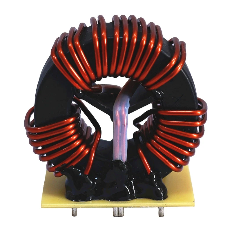
If you have questions about testing your HV transformer, or if you’re in the market for new equipment that’s built with insulation reliability as a top priority, I’m here to help. We’ve supplied HV transformers to utilities, industrial plants, and substation projects across the country, and our team can work with you to set up a maintenance plan that fits your needs. Don’t wait until your next outage to find out your insulation is failing—reach out to our team to discuss your transformer insulation testing requirements and how we can support your operations.
Transformer References
- IEEE Std 62-2015, IEEE Guide for Diagnostic Field Testing of Electric Power Apparatus.
- ANSI/IEEE C57.12.90-2015, Standard Test Code for Liquid-Immersed Distribution, Power, and Regulating Transformers.
- Del Vecchio, R. M., et al. Transformer Design Principles, 2nd Edition. CRC Press, 2010.
- Electrical Construction Maintenance (EC&M) Magazine. “HV Transformer Insulation Resistance Testing: Best Practices for Field Technicians.” June 2022.
Dongguan Hensiron Electric Co., Ltd.
As one of the most professional high-voltage transformer suppliers in China, we have world-leading production equipment and strong manufacturing capabilities. Please feel free to buy high quality high-voltage transformer made in China here from our factory. Customized orders are welcome.
Address: Building 4, Xinxing Industrial Zone, Wangao Road, Wanjiang Street, Dongguan City, China
E-mail: jessica@dghensiron.com
WebSite: https://www.dghensiron.com/
